Stated simply, the goal of Power Management is to derive as much computing time as possible from a set of batteries. In PQXT, this task can be difficult to perform due to the thousands of potential programs that may be run on the system. The PQXT power management software monitors activities performed by the target application and the hardware to try and determine how to transparently manage the system to prolong the battery life. Some of the techniques used to extend battery life are outlined in the following paragraphs.
If possible, use MS-DOS or the BIOS to manipulate the display. Poqet computers contain more than one video adapter, only one of which is available at a given time. If your program is not restricted to only one type of video adapter, calls to MS-DOS or the BIOS will take care of locating the correct video memory. If your program must have a specific type of video adapter, use the Extended BIOS functions and services to automatically change the video hardware to the correct type.
It is not necessary to attempt to remove "snow" by monitoring horizontal and vertical retrace bits. The hardware automatically arbitrates accesses to video memory.
In PQXT, the serial port can be disabled when it is not in use. Your application does not normally have to worry about enabling the serial port; however, it can make the Poqet-specific call for completeness -- see the Extended BIOS functions in Chapter 2. Once your application has finished using the serial port, it should call the BIOS to disable the UART and RS-232-C drivers, since they consume a great deal of power.
Communications programs usually need to remain active for the life of the connection. For this reason, it may be necessary for your application to disable or change the mode of the power management software to keep the system from stopping the CPU and missing incoming data. Your application can make this action automatic by using calls outlined in the Extended BIOS services.
Programs that are actively performing an operation, but want to give the user the ability to interrupt via Ctrl-C or other key combination, should not monitor the keyboard more than once per IRQ0. The time that elapses between each IRQ0 provides the program with a large interval to continue to complete tasks while still allowing a user to interrupt instantly if desired. Monitoring the keyboard too aggressively can cause power management to consider your program to be idle and stop the system. See Chapter 2 for an explanation of how to use the "Wake Up" service of Extended BIOS (function 02H, service 07H) to reactivate the system.
Your application may turn power management on or off via program calls, if necessary. For most applications, power management should be left active to prolong battery life.
In some cases, programs may become idle, but are not detected as being idle by the power management software. In these cases, programs may use the "User Idle" extended BIOS call to declare themselves idle and relinquish control. An example of this situation could be a program that is waiting for a semaphore from an IRQ0 interrupt routine. In this example, the main program should invoke the "User Idle" extended BIOS call to declare itself idle. When the IRQ0 routine detects the correct situation, it sets or clears the semaphore and makes the "Wake Up" extended BIOS call to reactivate the system.
In other cases, programs may wish to remain active, but are continuing to do things that cause the power management software to detect an idle state and take control of the system. An example of this situation could be a program that is reformatting text in the background while scanning the keyboard for new text from the user. In this case, it may be necessary to have the program declare itself still active by using the "Wake Up" service of Extended BIOS (function 02H, service 07H) once every IRQ0 interrupt until the background task has completed.
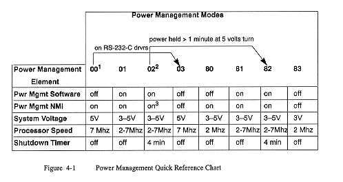
Table 4-1 lists the power management modes currently supported by the BIOS. All of these modes are accessible through the extended BIOS interface as described in Chapter 2, while three of them are available through keyboard entry. The BIOS will automatically change from one mode to another in certain circumstances, as explained in the following paragraphs.
Table 4-2 Power Management Modes
        Mode        Function
        -------------------------------------------------------------------
        00H (1)     The power management software is disabled and the
                    system is left at the full voltage level of +5 volts.
                    Beginning with BIOS 1.30, the power management NMI is
                    still enabled.  Int 16H, which is the keyboard
                    interrupt, is no longer trapped by the PQXT.

        01H         If the BIOS detects that the system is idle, it causes
                    the PQXT to enter display mode. In this mode, the CPU
                    clock stops, then restarts to process timer ticks and
                    keystrokes.  The BIOS is free to adjust the system
                    voltage to balance power consumption and performance.

        02H (2)     This is the default power management mode on boot-up.
                    The BIOS functions as in mode 1, but after being in
                    display mode for approximately four minutes, the system
                    turns off.  The display is then turned off, the
                    RS-232-C drivers are disabled, the baud clock is turned
                    off and keyboard interrupts are disabled.  System RAM
                    and video RAM are preserved and the time of day counter
                    is maintained.  The system may be turned back on using
                    the I/O key or by means of a program interface.

        03H         This mode was added in BIOS 1.30. The power management
                    software is disabled, the system is placed at full
                    voltage and the power management NMI is removed.  This
                    mode is used to enhance operation of communications
                    programs.  It is automatically selected when the system
                    is in mode 00H and the RS-232-C drivers are enabled, or
                    when the system is in mode 83H and an access is made to
                    a RAM card.

        80H (3)     Same as mode 00H, except the system is held at a reduced
                    voltage of 3 volts to reduce power consumption.  The
                    system voltage changes to full voltage when accessing
                    memory cards, but returns to the reduced voltage state
                    afterwards.  This mode is known as the communications
                    mode.  The processor operates at reduced speed, so be
                    aware that when running the serial port at high speeds
                    the processor may not be able to keep up.  Mode 80H is
                    available beginning with BIOS 1.30.

        81H         Same as mode 01H, except the system is held at a reduced
                    voltage of 3 volts to reduce power consumption.  The
                    system voltage changes to full voltage when accessing
                    memory cards, but returns to the reduced voltage state
                    afterwards.  Mode 81H is available beginning with
                    BIOS 1.30.

        82H         Same as mode 02H, except the system is held at a reduced
                    voltage of 3 volts to reduce power consumption.  The
                    system voltage changes to full voltage when accessing
                    memory cards, but returns to the reduced voltage state
                    afterwards.  Mode 82H is selected automatically by the
                    BIOS if the system is operating in mode 02H and system
                    voltage is constantly at 5 volts for more than one
                    minute.  Mode 82H is available beginning with BIOS 1.30.

        83H         The power management software is disabled and the power
                    management NMI is removed. The system is initially
                    placed in a reduced voltage state.  Your application
                    must take care in using this mode, since an access to
                    a memory card will effectively turn this mode into
                    mode 03H.  Mode 03H results because the power management
                    NMI is disabled and there is no way to return the
                    system to the reduced voltage state of 3 volts auto-
                    matically.  Mode 83H is available beginning with
                    BIOS 1.30.

        Notes:  1. Same as the keyboard Power Management Off mode
                2. Same as the keyboard Power Management On mode
                3. Same as the keyboard Power Management Communications mode
Figure 4-1 at the end of the chapter gives additional reference
information on power management modes.
PQXT can operate at three power levels which are controlled by typing the commands listed below.
Note: