Chapter 8
Poqet Video
PQXT has a built-in 80 x 25-character LCD display which emulates both
the CGA and MDA standards. The display also contains a status line
located at the bottom of the display screen. The default mode at power-
up/reset is MDA.
Poqet has made the display driver in the PQXT as compatible as possible
with the standard CGA and MDA display adapters. There are factors,
however, which forced Poqet to deviate from these standards. The
purpose of this document is to outline departures from the CGA and
MDA standards and provide an explanation of each case. Where
applicable, workarounds are included.
Color in Text Mode
The display technology used in the Poqet PQXT does not support
color. To be compatible with the CGA standard, special
provisions were designed into the display hardware to deal with
the color bits specified in the attribute byte.
Each pixel location is black when turned "on" and white or
invisible when turned "off". The CGA emulation hardware has
been designed to convert color information into monochrome for
display on the LCD screen.
If the three-bit value of the foreground color is equal to the
bit value of the background color and the intensity bit (bit 3)
is not set, then the character cell will be blank (that is, no
LCD pixels will be visible). The one exception to this is when
both values are 1 1 1. In this case, all pixels in the character
cell will be visible yielding a solid black block.
If the background bits are all set (1 1 1) and the foreground is
000, then the character will be inverse and displayed as a white
character drawn in a black box.
When blinking is disabled in CGA control register, bit 7 is
cleared in the 6845 register, bit 7 of the attribute byte
controls the intensity component of the background on a CGA
adapter. Clearing this bit will stop display blinking on the
PQXT Models 0164-0168 and 1164, but there will be no observable
change in display color mapping.
The CGA color select register is not implemented in the PQXT.
Writing to this register has no effect.
Workaround
Programs that write directly to CGA hardware should be
configured as a CGA adapter attached to a monochrome display, if
possible. Make sure the attribute selected for characters
appears as desired.
Selecting BIOS text mode 02h (00h for 4Ox25) doubles the
characters to 8xl6 pixel size. This command works only while
the PQXT is in CGA mode.
Display Pages in Text Mode
The CGA specification calls for text mode display pages to start
on 4K paragraph boundaries. The 6845 CRT controller, however,
does not have this restriction. On a 6845-based CGA adapter,
the display pages could start at any even byte address. Poqet
has restricted the CGA emulator on the PQXT to conform to the
published standard.
Below is a list of allowed values for the 6945 memory start address
register high byte:
Page  8Ox25   4Ox25
0     00h     00h
1     10h     08h
2     20h     10h
3     30h     18h
4     n/a     20h
5     n/a     28h
6     n/a     30h
7     n/a     38h
Text Mode Intensity Attribute
Bit 3 of the character attribute byte is used to set character
intensity on a CGA adapter. If bit 3 is set, then an alternate
form of the character is displayed. An LCD display pixel has no
intensity; it can only be on or off. By using an alternate
character style, the user is able to discriminate between the
two types of characters. On the PQXT Models 0164-0168 and 1164,
the alternate character is a single-dot-width character rather
than a double-dot-width character.
Workaround
None needed.
640 x 200, 2-color graphics mode
On a CGA display, one bit corresponds to each pixel location.
When this bit is set, the pixel assumes the foreground color.
If the bit is not set, the pixel assumes the background color.
On the PQXT Models 0164-0168 and 1164, the background color is
always white (no LCD pixel visible), and the foreground color is
always black (the LCD pixel is visible).
Workaround
CGA color select register changes will not cause any change on
the display.
320 x 200, 4-color graphics mode
On a CGA display, each pixel location is described by two
consecutive bits. These two bits allow the pixel to assume the
background color (when both are 0) and three other colors.
In implementing this mode on the PQXT Models 0164-0168 and 1164,
Poqet made it functionally equivalent to the 640 x 200, 2-color
graphics mode. Each bit will still map directly to one pixel.
If the two bits used to describe the graphics location are 00,
then no pixels are visible. If the bits are 1 1, two pixels
will be visible. The values 01 and 10 will be a pattern of one
visible pixel adjacent to a pixel location that is not visible.
Below is a description of how a solid area would appear for each
of the four combinations:
Bit Pattern  Appearance
00           White - no LCD pixels visible
01           Grey - every other LCD pixel visible
10           Grey - every other LCD pixel visible
11           Black - all LCD pixels in the area visible
Note that an area described by the pattern 01 is barely
distinguishable from one described by a pattern of 10. Areas
shaded as 01 or 10 appear as vertical stripes that are 1 pixel
wide.
Workaround
None.
The LCD cable connects the hinged LCD panel to the main unit.
It is located on the right side of the computer above the right
hinge. You can see the cable only when the computer is open.
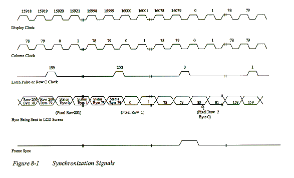
There are 80 display clocks for every row clock.
Column clock 1 runs for the first 40 display clocks and then
stays low for the other 40 display clocks of a row.
Column clock 2 runs for the second 40 display clocks and is low
for the first 40 display clocks of a row.
Phase changes every 7 or 9 row clocks on the falling edge of the
row clock. These are programmable. Frame sync occurs every 201
row clocks. VCC is system power.
LCD power and #LCD Power are digital signals from ASICs that are
in their respective active state when the display is enabled.
Contrast is a programmable-duty-cycle digital signal used for
screen contrast.
Battery connects directly to your system batteries.
GND is system ground.
Speaker data is digital speaker data.
Pins are numbered from right to left looking at screen side of
upper housing.
Pin Assignments of LCD Cable
Pin      Signal name
1        Data (0)
2        Data (1)
3        Data (2)
4        Data (3)
5        Data (4)
6        Data (5)
7        Data (6)
8        Data (7)
9        Column Clockl
10       Column Clock2
11       Row Clock (Latch Pulse)
12       Phase
13       Framesync
14       vcc
15       LCD Power
16       #LCD Power
17       Contrast
18       Battery
19       GND
20       Speaker Data
 Poqet has emulated the 6845 CRT controller on the PQXT. The
following text describes those features of the 6845 that have
been implemented differently than on a standard CGA adapter.
3D4h 6845 Index register
This register is used to point to 18 registers inside the 6845
denoted 6845(0) - 6845(17). Poqet has implemented registers 10,
11, 12, 14, and 15. Those registers not implemented deal with
operational aspects of a CRT.
Workaround
None needed.
6845(12) (bits 5-3) Memory start address
(Bits 0,1,2 are ignored)
The CGA text mode specification calls for text mode display
pages to start on 4K paragraph boundaries. The 6845 CRT
controller, however, does not have this restriction. On a 6845
based CGA adapter, the display pages could start at any address.
Poqet has restricted the CGA emulator on the PQXT to conform to
the published text standard.
Although there is only one display page available for CGA
graphics modes, it is possible to change the memory start
address registers to another address. Since there are 384 bytes
of memory at the bottom of the graphics page, it would be
possible to change the start address to take advantage of the
extra memory. PQXT does not support the ability to change the
start address in graphics mode.
Workaround
Use BIOS calls for video services
3D8h - Control Register
Bit 2 (select B&W mode) is ignored since the PQXT is always in
black and white.
Bit 5 (background color) will not cause a change in background
appearance when set to 0.
Bit 3 (enable video) will yield the same result as on a CGA
adapter. However, on PQXT this bit also enables the control
signals and power to the LCD display circuits. When bit 3 is 0
(the power-up/reset state), the display clock oscillator stops
running and power is removed from the display circuits.
Workaround
Disable the display via bit 3 only when wishing to conserve power.
3D8h - Stcttus Register
The PQXT display logic does not perform any vertical retrace.
There are programs, however, that will monitor this register in
an attempt to perform synchronized access to the CGA hardware.
To avoid problems with such programs, bit 0 and bit 3 will
change states each time a read is made to this 1/0 port.
However, unlike the original IBM CGA adaptor, display
interference can't be corrected by monitoring these bits.
Despite this interference, the LCD display is still able to
provide a clean image.
Workaround
Do not attempt to perform synchronized access as this will slow down
video throughput.
MDA Emulation
Character Cell Size: The MDA standard uses a character cell that
is 9xl4 pixels. The PQXT display can only accommodate an 8x8
character cell. The character set used for MDA is the same as
the CGA character set. There are still 25 rows of 80 characters,
even though there are fewer pixels than on an MDA monitor.
Workaround
The only time this could cause a problem is when selecting a
cursor size. The most common MDA cursor size uses the scan lines
0Ch and 0Dh to display the cursor. However, these values are
out of the 8x8 cell region. The display hardware performs a
translation on cursor start and end scan line values to scale
them into the 8x8 cell. See the discussion in the 6845 CRT
Controller (MDA Mode) section below for a table of translated
cursor values.
Text Mode Intensity
Attribute bit 3 of the character attribute byte is used to set a
characters intensity on an MDA adapter. If bit 3 is set, then
an alternate form of the character is displayed. An LCD display
pixel has no intensity - it can only be on or off. The use of
an alternate character style will still allow the user to
discriminate between the two types of characters. On PQXT
Models 0164-0168 and 1164, the alternate character is a
single-dot-width character rather than a double-dot-width
character.
Workaround
None needed.
Poqet has emulated the 6845 CRT controller on the PQXT. The
following text describes those features of the 6845 that have been
implemented differently than on a standard MDA adapter.
3B4h / 3B5h - 6845 Index Regiqter
This register is used to point to 18 registers inside the 6845
denoted 6845(0) - 6845(17). Poqet has implemented registers 10,
11, 12, 14, and 15. Those registers not implemented deal with
operational aspect of a CRT.
Workaround
None needed.
6845(10) (bits 3-0) Cursor start register
Since the character cell size on the PQXT display is 8x8 pixels
instead of 9xl4 pixels, translation hardware was designed into
the display driver to change MDA cursor start line into an 8x8
compatible line number.
Workaround
Use BIOS calls for video services. Consult the table below when
writing directly to the 6845(10) register:
Value                          Value
written to 3B5h                stored in 6845(10)
0h                             0h
lh                             0h
2h                             lh
3h                             lh
4h                             2h
5h                             2h
6h                             3h
7h                             3h
8h                             4h
9h                             4h
Ah                             5h
Bh                             5h
Ch                             6h
Dh                             7h
Eh                             7h
Fh and above                   7h
6845 113 (bits 3-0) Cursor end register
Since the character cell size on the PQXT display is 8x8 pixels
instead of 9xl4 pixels, translation hardware was designed into
the display driver to change MDA cursor end address into an 8x8
compatible address.
Workaround
Use BIOS calls for video services. Consult the table below when
writing directly to the 6845 register:
Value                                Value
written to 3B5h                      stored in 6845 (11)
0h                                   0h
lb                                   0h
2h                                   lb
3h                                   lb
4h                                   2h
5h                                   2h
6h                                   3h
7h                                   3h
8h                                   4h
9h                                   4h
Ah                                   5h
Bh                                   5h
Ch                                   6h
Dh                                   7h
Eh                                   7h
Fh and above                         7h
6845(12) (bits 5-3) - Memory start address
The MDA standard allows for only one page of text. The 6845,
however, will allow the start address to be changed to any byte
boundary. This would allow an application to take advantage of
the extra 192 character positions at the end of display memory.
The PQXT does not support this. The only valid value for this
register is 00h. Writes made to the register are ignored in MDA
mode.
Workaround
- Use BIOS calls for video services
- Do not attempt to place any value other than 00h in this register.
3B8b - Control Register
Bit 3 (enable video) will yield the same result as on an MDA
adapter. However, on the PQXT this bit also controls the control
signals and power to the LCD display circuits. When bit 3 is 0
(the power-up/reset state), the display control signals are
disabled and power is removed from the display circuits.
Workaround
Disable the display via bit 3 only when wishing to conserve
power.
3D8h - Status Register
The PQXT display logic does not perform any vertical retrace.
There are programs, however, that will monitor this register in
an attempt to perform synchronized access to the MDA hardware.
To avoid problems with such programs, bits 0 and bit 3 will
change states each time a read is made to this I/0 port.
Workaround
Do not attempt to perform synchronized access as this will slow
down video throughput.
Anomalies
The flrst character (upper left comer) and last character (ower
right comer) of the display do not blink.
Blinking Attribute
PQXT is able to provide its long battery life in part by
powering down the CPU between keystrokes. This can cause a
problem with the blinking attribute at certain times. For
instance, unless the CPU is powered up any character with the
blinking attribute set will not operate. However, when any key
is pressed the CPU is powered up and the character blinking is
then enabled.
Note: The blinking attribute will operate normally
when the Power Management software is off.
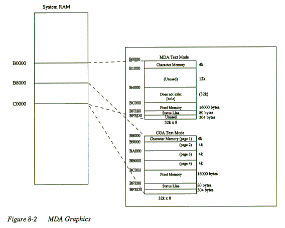
BC000 space (bit mapped graphics)
One way PQXT saves power is to incorporate a bit-map pixel
memory that is used for the image that appears on the screen.
In text mode, characters and attributes are written to character
memory locations B8000 to BBFFF (B0000 to B0FFF in MDA mode). As
programs write characters to this character memory, the display
controller converts the characters into bit-maps that appear in
the pixel memory and on the display. This pixel memory is
located at addresses BC000 to BFFFF.
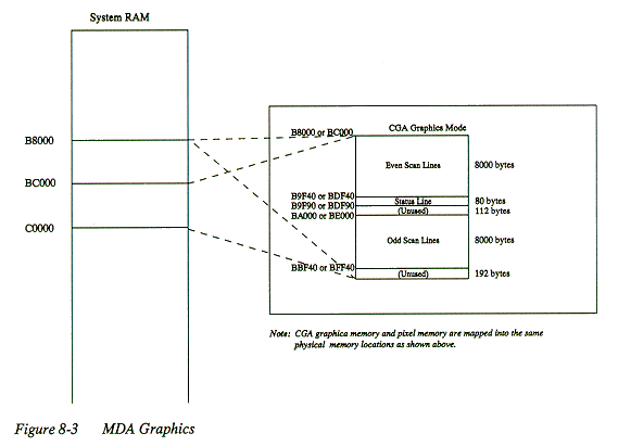
In CGA grapics mode, the pixel memory is the same as the CGA
even and odd scan line graphics memory areas. Since the same
physical memory is used for both memeory areas, reads and writes
to B8000-BBFFF have the same efffect as reads and writes to
B8000-BBFFF for the same offset. For example, a write to
location B8055 is the same as a write to BC055.This is
illustrated in Figure 8-2, CGA graphics memory.

The bit mapped status line also appears within the pixel memory.
In MDA or CGA text modes the status line is located in locations
BFE80 to BFECF. In CGA graphics mode, the status line memory is
located in locations B9F90 to B9FDF. Uuustrations of the status
line locations for the display modes are shown in Figures 8-2
and 8-3 below.

Copyright (c) 1989, 1990, 1991, 1992 Poqet Computer Corporation.
All rights reserved.
Filename: PoqetPC/docs/poqetpc/techref/chapter8.html
Date Created: 23 May 98, Last Modified: 23 May 98
Created by Bryan Mason
- E-Mail: poqetpc<at>bmason<dot>com


